If you have spent any time around manufacturing floors lately, you have probably noticed that the line between prototyping and full scale production is getting blurrier by the day. Additive manufacturing used to be the cool kid on the block for making one off prototypes or really wild geometries that no CNC could touch. But when the conversation shifts from making ten parts to making ten thousand parts, the math changes in a hurry. That is where a lot of engineers hit a wall. They love the freedom of design that comes with 3D printing metals like titanium or stainless steel, but they need the cost per part and cycle times that traditional tooling offers. The secret that many high performance industries are leaning on right now is not about choosing one over the other. It is about a clever hybrid workflow that brings MIM, or Metal Injection Molding, into the same conversation as additive manufacturing.
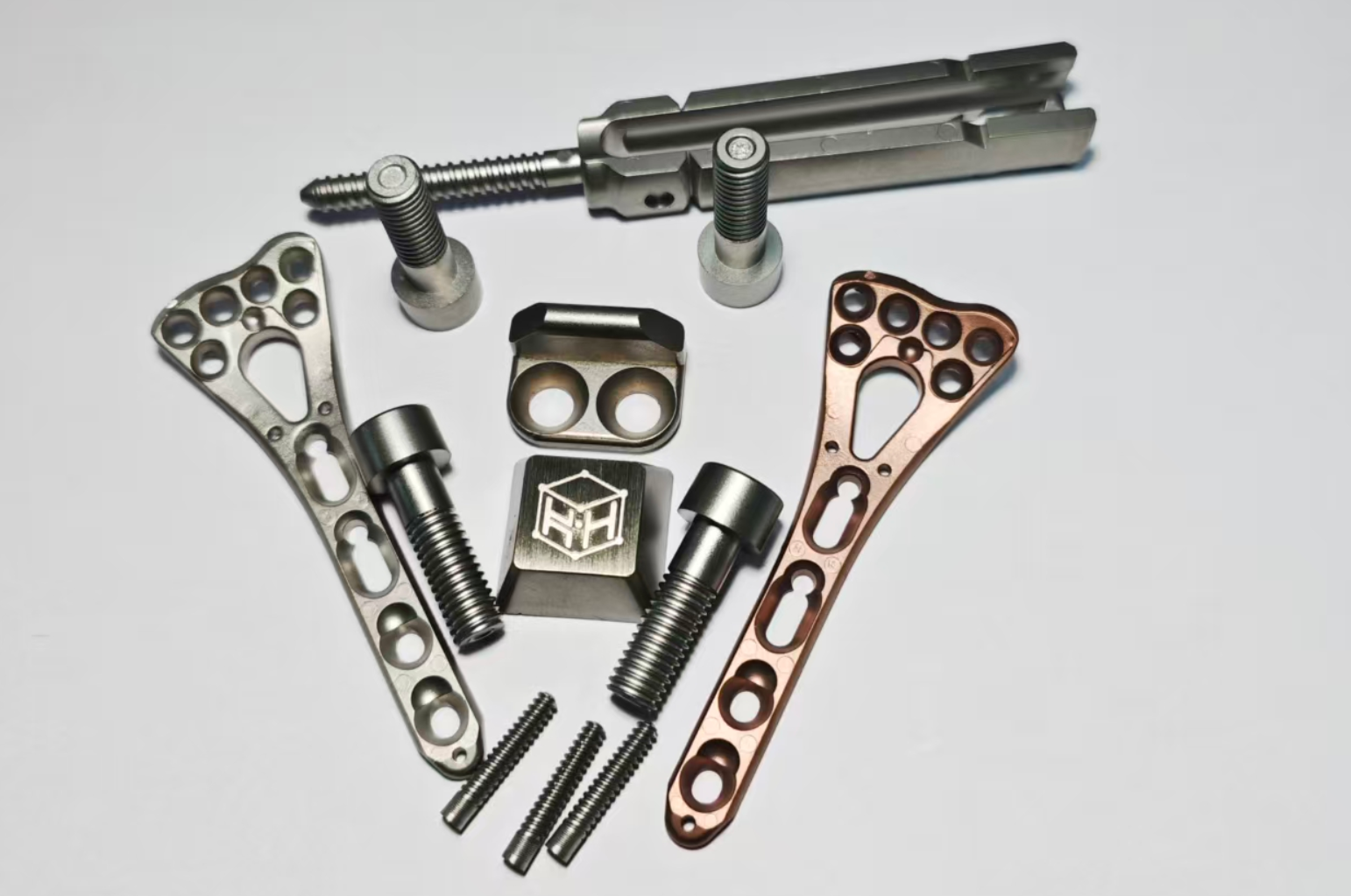
For small, intricate components, things like watch bezels, surgical tool jaws, or even those tiny locking levers in a folding knife, the geometry is often too complex for cheap machining and the volume is too high for laser powder bed fusion to be economical. This is exactly the sweet spot where integrating MIM alongside AM stops being a theory and starts being a serious competitive advantage. It allows you to use 3D printing for the heavy lifting of design iteration and validation, and then switch gears to MIM for the heavy lifting of actual production output. It sounds simple on paper, but pulling it off smoothly requires understanding where the pitfalls are in each process.
The Fundamental Difference in Shrinkage and Scale
Let's get one thing straight right out of the gate: metal injection molding is a game of controlled shrinkage. You are mixing very fine metal powder with a binder system, injecting it into a mold that is oversized compared to the final part, and then spending a lot of time and heat removing that binder before you sinter the metal to full density. The part that comes out of the sintering furnace is significantly smaller than the one that went in. In fact, it usually shrinks by about fifteen to twenty percent linearly. If you are an engineer who is used to the near net shape accuracy of a laser powder bed fusion machine, that level of shrinkage can feel like voodoo magic. Additive manufacturing, on the other hand, gives you a part that is pretty close to the CAD file right off the build plate, maybe with a little distortion from residual stress, but nothing like that massive volumetric change.
This is where the integration gets tricky. You cannot just take an AM optimized design file and send it over to the MIM department. That beautifully lightweight topology optimized bracket with all those organic, flowing curves? It might be a nightmare to eject from a mold. The undercuts that are a breeze in 3D printing because you just dissolve the supports away become expensive side actions or slides in a mold tool. When you are designing for this dual strategy, you have to keep one eye on the freedom of the laser and the other eye on the parting line of the mold. The most successful integrations treat the AM part as the functional prototype that proves the concept, and then the team sits down to tweak that geometry specifically for moldability without sacrificing the critical functional surfaces. You are essentially translating a file from the language of additive to the language of injection.
Why Start With Additive If MIM Is the End Goal
It might seem like an extra step. Why not just cut a MIM tool and get on with it? The answer almost always comes down to speed of development and the cost of being wrong. A MIM tool is a precision piece of steel that can easily cost tens of thousands of dollars and take eight to twelve weeks to build and sample. If you put that tool into the press and then realize that the snap fit feature is a little too brittle or that the wall thickness is causing a sink mark opposite the rib, you are in for a very expensive and very slow modification process. That kind of timeline just does not fly in medical device development or consumer electronics.
By front loading the development cycle with additive manufacturing, particularly with materials that mirror the MIM feedstock, you can iterate like crazy. You can print ten different variations of a hinge geometry in a week using the same metal powder composition that will eventually be used in the MIM process. You can test the tactile feel, the breakaway torque, and the fatigue life without ever touching a mold base. Once the design is locked and the validation testing is signed off, that is when you pull the trigger on the tooling. This is especially relevant for materials that are popular in both worlds, like 17-4PH stainless steel or low alloy steels. You are not just guessing that the part will work in metal. You are proving it with a physical metal part long before the production line is ready.
This is the kind of workflow that companies focused on complex small parts, like Kyhe Tech, navigate regularly. They understand that the surface finish requirements and tolerance bands are different between the two processes. A part that looks and feels perfect coming out of a 3D printer might need a subtle draft angle adjustment to release from a mold efficiently. Integrating these processes means you are designing the part twice, once for the prototype and once for the millions.
A Quick Comparison of AM and MIM in Production
When you are trying to decide whether to keep a part in additive manufacturing or move it over to metal injection molding, it helps to look at the numbers side by side. The table below lays out the practical differences between the two approaches for a typical production run of small metal components. Keep in mind that these are general guidelines and the exact numbers will shift depending on the complexity of the geometry and the specific alloy.
|
Feature Comparison |
Additive Manufacturing (Laser Powder Bed) |
Metal Injection Molding (MIM) |
|
Ideal Annual Volume |
1 to 5,000 units |
10,000 to 1,000,000 plus units |
|
Cost Per Part at High Volume |
High (Limited by machine time) |
Low (Amortized tooling cost) |
|
Design Freedom |
Extremely High (Organic shapes, lattices) |
Moderate (Must account for ejection) |
|
Surface Finish As Produced |
Moderately Rough (Ra 5 to 10 microns) |
Smooth (Ra 1 to 3 microns) |
|
Tolerance Capability |
Plus or minus 0.002 to 0.005 inches |
Plus or minus 0.001 to 0.003 inches |
|
Lead Time for New Design |
Days (No tooling required) |
8 to 12 Weeks (Tooling fabrication) |
|
Material Waste |
Low (Recyclable powder) |
Very Low (High feedstock utilization) |
Looking at this, the strategic overlap becomes obvious. Additive manufacturing wins the race for speed to market and complex internal features. MIM wins the race for unit economics once the volume ramps up and the design is frozen. The smartest manufacturing strategies treat these two columns not as rivals but as different gears in the same transmission. You shift between them based on where you are in the product lifecycle.
Dialing In the Tolerances for High Volume MIM Production
Tolerance is the word that scares the living daylights out of designers who are new to metal injection molding. In additive manufacturing, you can usually hold a tolerance of plus or minus a few thousandths of an inch on a well calibrated machine, but you are building that part layer by agonizing layer, which takes time and money. In MIM, once the tool is dialed in and the sintering furnace is profiled correctly, you can hold extremely tight tolerances, often plus or minus half a percent of the dimension, across hundreds of thousands of cycles, all for pennies per part. But achieving that level of precision requires a deep understanding of how the part distorts during debinding and sintering.
If you are bringing an AM design into the MIM space, you absolutely must run a sintering simulation. These software tools take the green part geometry and predict where the part will slump or warp during the thermal cycle. This is non negotiable for complex geometries. You might have a small medical staple that looks perfect in the CAD file, but when it shrinks fifteen percent, that uneven mass distribution will cause the legs to twist inward or outward. The fix is often to add what are called setters, which are custom ceramic fixtures that hold the part in a specific position during sintering. But those fixtures cost money and take up space in the furnace. The better approach is to use the insights from your AM prototype testing to identify where you can add or remove a tiny fillet or rib to help the part stay true on its own during the shrink. It is a delicate dance of mass balance, something that is rarely a concern with an AM part sitting on a rigid build plate.
The Post Processing Factor Nobody Talks About
There is a huge misconception that once a MIM part comes out of the sinter furnace, it is ready to ship. That could not be further from the truth, especially when you are talking about components that interface with other precision mechanisms. MIM parts have gate vestiges, they have parting line flash, and they have a surface finish that, while better than cast metal, might still need refinement. This is actually where the additive manufacturing mindset has started to bleed over into the MIM world in a very positive way.
In additive manufacturing, we have gotten very comfortable with the idea that the part is not done when the laser turns off. There is a post processing queue that includes heat treatment, support removal, and surface finishing like bead blasting or tumbling. In MIM, that same level of care is required, just at a much higher volume. You are not tumbling a tray of ten parts. You are tumbling a drum of ten thousand parts. Providers who excel at the integration of these technologies, such as Kyhe Tech, have invested heavily in automated post processing lines that can handle that kind of throughput without compromising on the delicate features of a tiny complex part. If you design a feature that is too fragile to survive a high energy centrifugal barrel finishing process, you have essentially designed a part that cannot be mass produced economically. Integrating AM and MIM means understanding the journey of the part all the way through to the final inspection tray, whether that involves a CMM check for a single prototype or an optical sorting system for a continuous stream of production units.
Designing for Both Worlds Without Losing Your Mind
So how do you actually sit down and design a part that can be prototyped quickly via additive and then scaled seamlessly into MIM? The trick is to build a ruleset into your CAD process early on. You want to avoid deep, narrow holes that are hard to clean in MIM tooling. You want to maintain a relatively uniform wall thickness to prevent warping during the sintering shrink. These are exactly the kinds of things that additive manufacturing tolerates much better than MIM does.
But there is also a crossover benefit. The design for additive manufacturing principles that emphasize avoiding sharp corners and large mass concentrations actually align beautifully with good MIM design practices. A part that has been topology optimized to remove mass will likely also sinter more uniformly because you have already eliminated the thick, heavy sections that cause thermal lag. If you can design a part that uses an organic lattice or a clever hollow structure to reduce weight, that same part, when translated to a MIM tool, will consume less material, cost less in powder, and shrink more predictably. It is a beautiful feedback loop. Use additive to find the perfect shape. Use that shape to create a MIM part that is lighter and more cost effective than anything your competitors are making with traditional machining. It is not about additive replacing MIM or vice versa. It is about using the best tool for the right stage of the product lifecycle and making sure your designs are fluent in both languages.
Where This Hybrid Approach Shines Brightest
If you look at the products that benefit most from this dual approach, they are almost always in the realm of small, complex, and high value. Think about the micro gears inside a surgical stapler. The first few thousand units might be run on a laser powder bed machine while the surgical team validates the ergonomics and the firing sequence. During that time, the MIM tool is being cut. Once the design is frozen, the production line switches over and starts churning out tens of thousands of those gears per month at a fraction of the AM cost. The patient or the surgeon never knows the difference, but the company's bottom line certainly does.
This strategy also plays a huge role in sustainability, which is becoming non negotiable in modern manufacturing. MIM feedstock utilization is incredibly high compared to subtractive machining, often exceeding ninety five percent. When you combine that with the fact that additive manufacturing only uses the powder it needs for that specific geometry, you have a manufacturing ecosystem that generates very little waste. It is a responsible way to make things, and it is the direction the industry is moving. The ability to navigate both the digital flexibility of 3D printing and the economic efficiency of metal injection molding is what separates the innovators from the rest of the pack. It means you are never stuck. You can always find the right tool for the right volume.
Table of Contents
- The Fundamental Difference in Shrinkage and Scale
- Why Start With Additive If MIM Is the End Goal
- A Quick Comparison of AM and MIM in Production
- Dialing In the Tolerances for High Volume MIM Production
- The Post Processing Factor Nobody Talks About
- Designing for Both Worlds Without Losing Your Mind
- Where This Hybrid Approach Shines Brightest